
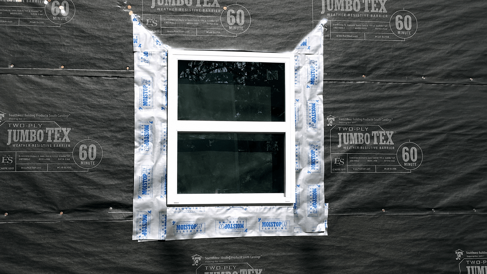
Window Flashing Standards for Elastomeric Stucco Walls
Architects and installers who have watched a stucco wall assembly fail rarely point to the finish coat as the culprit. The failure almost always traces back to a window opening, and more specifically to a flashing sequence that was incomplete, out of order, or incompatible with the weather-resistant barrier behind the cladding. Window openings interrupt the continuity of every layer in the wall assembly simultaneously, and getting that transition right requires a clear understanding of sequencing, material compatibility, and drainage principles.
This article explains the correct approach to window flashing for stucco walls: the role of the WRB, the sequencing logic at sill, jamb, and head, how a drainage plane changes the detailing requirements, and the failure modes that show up most often in the field.
TLDR
Window openings are the highest-risk location in a stucco wall assembly, and the answer is a strict flashing sequence: sill pan first, jamb flashing second, head flashing last, with each layer lapping over the one below it so water always sheds outward and downward into the drainage plane. Reversing that order results in a reverse lap, one of the most common causes of chronic moisture intrusion at windows. The WaterWay 7mm Rainscreen Mat drains water 50 times faster than standard weather-resistant barriers, exceeds 247 perms per ASTM E-96, and maintains 90% open space; Stuc-O-Flex achieves 105% elongation and 127.9 PSF bond strength per ASTM C-297, so the finish flexes at the window perimeter while the flashing and WRB manage the bulk water.
Why Window Openings Are the Highest-Risk Location in a Stucco Assembly
Every wall has a primary drainage plane, the layer behind the cladding where water that penetrates the surface is meant to be collected and directed downward and out. In a stucco assembly, that plane is typically the weather-resistant barrier (WRB) installed over the sheathing. A window opening punches through every layer of that assembly at once: the sheathing, the WRB, the lath, and the finish coat all terminate at the rough opening, and each termination is a potential water entry point.
What makes window openings particularly vulnerable is geometry. Water that reaches the WRB anywhere above the opening will travel downward until it hits the head flashing. Water that infiltrates at the jambs can travel laterally. Water that pools at the sill has nowhere to go except into the rough opening or the wall cavity if the sill flashing is improperly sloped or unsealed. A correct flashing sequence addresses all three conditions simultaneously, creating a continuous, lapped system where every component sheds water to the component below it and ultimately to the drainage plane.
The stakes are higher in climates with sustained rainfall and wind-driven moisture. Projects in the Pacific Northwest, for example, face consistent pressure on window transitions because bulk water exposure is frequent and prolonged. But the same detailing principles apply in any climate where moisture management is a priority in specifications.
The Correct Flashing Sequence: Sill, Jamb, and Head
The flashing sequence is not interchangeable. The correct order exists because each component must lap over the one below it, so water is always directed outward and downward rather than into the assembly. Installing components out of sequence creates reverse laps, which are among the most common sources of chronic moisture intrusion in stucco-clad buildings.
Sill flashing is installed first. The sill pan must slope toward the exterior to drain any water that enters the rough opening. Pan flashing should extend up the jambs and be sealed at the corners. The front edge of the pan should terminate at or beyond the face of the sheathing so water exits the assembly rather than draining back into the wall cavity. This is the foundational component of the entire window transition.
Jamb flashing is installed second, lapping over the sill pan. Jamb flashing runs vertically from the sill pan upward, integrating with the WRB on the face of the sheathing. The WRB must lap over the top of the jamb flashing at each side, not be tucked behind it. Jamb flashing should be sealed to the window frame at the interior edge and left free to drain at the exterior edge.
Head flashing is installed last, lapping over the jamb flashing and the WRB. The head flashing directs water away from the top of the rough opening and over the face of the cladding. In a stucco assembly, head flashing typically terminates with a drip edge that projects beyond the face of the lath to prevent water from tracking back under the stucco. The WRB above the window should lap over the top of the head flashing, completing the continuous drainage path from top to bottom.
Each layer in this sequence sheds water to the layer below it. Changing any step creates a reverse lap, allowing water to migrate into the assembly.
WRB Integration and the Role of the Drainage Plane
The weather-resistant barrier is not simply a backup membrane. In a correctly detailed stucco assembly, the WRB is the primary drainage plane, and the flashing at every window opening must integrate with it continuously. Gaps, tears, or improper lapping at window transitions defeat the WRB’s function at the locations where it matters most.
At the rough opening perimeter, the WRB should be cut and folded into the opening, with the sill portion folded down onto the sill pan and the jamb and head portions lapped correctly over the flashing components as described above. Any penetrations or fasteners through the WRB within the transition zone should be sealed. Tape or flashing tape compatible with the WRB material should be used at all seams and transitions.
When a drainage mat is incorporated into the wall assembly, the detailing requirements at window transitions become more specific. A drainage mat, such as the WaterWay Rainscreen Mat, creates a continuous cavity between the WRB and the lath, allowing bulk water that reaches the WRB to drain freely downward and exit at the base of the wall. This cavity needs to be managed at window openings so that water traveling down the drainage plane is directed outward rather than into the rough opening.
At the sill, the drainage mat should terminate above the sill flashing and be detailed so that water exiting the mat cavity is directed onto the sill pan and out of the assembly. At the head, the drainage mat should allow water traveling down the WRB above the window to continue past the head flashing without being trapped. When a rainscreen assembly is specified, the installer should confirm that the drainage plane remains continuous and unobstructed through the window transition zone.
The WaterWay 7mm Rainscreen Mat drains water 50 times faster than standard weather-resistant barriers and exceeds 247 perms moisture vapor transmission per ASTM E-96, with 90% open space within the cavity. It exceeds ICC/IRC AC-38 acceptance criteria for weather-resistant barriers. These documented figures matter at window transitions specifically because the drainage plane must remain functional even when bulk water is concentrated at the opening. For more on how rainscreen assemblies manage moisture at the wall assembly level, see The Importance of a Ventilated Facade in Humid Climates and Benefits of Rainscreen Drainage Mats in Humid Climates.
Sealant Joint Requirements at Stucco-to-Window Transitions
Flashing alone does not complete the window transition. A correctly specified sealant joint at the perimeter of the window frame is required to prevent water from tracking between the frame and the surrounding stucco finish. Without it, even a correctly sequenced flashing assembly can allow water entry at the finish coat interface.
The sealant joint at a stucco window transition serves a specific purpose: it accommodates differential movement between the window frame and the stucco cladding while maintaining a continuous water seal. Window frames and stucco expand and contract at different rates. A sealant joint that is too thin, applied without a backer rod, or specified with an incompatible material will fail in shear as the assembly moves, opening a gap at the most vulnerable location in the wall.
A backer rod should be installed to control joint depth and provide a working surface for the sealant. The joint should be wide enough to accommodate anticipated movement. The sealant material must be compatible with both the window frame material and the elastomeric stucco finish. Applying sealant over an incompatible primer, or over a surface that has not been properly cleaned and prepared, will result in adhesion failure regardless of the sealant’s inherent performance.
For stucco assemblies using an elastomeric acrylic finish, the sealant selection should account for the flexibility of the surrounding cladding. The finish coat achieves 105% elongation per ASTM testing, which means the surrounding material will move with the building rather than cracking. A rigid sealant at the window perimeter will become the weakest link in the transition, failing before the cladding does.
Common Failure Modes to Avoid
Understanding what goes wrong is as useful as understanding what should go right. The following failure modes account for a significant share of moisture intrusion problems at stucco window transitions.
Reverse laps in the WRB or flashing.
This is the most common sequencing error. When the WRB is installed before the flashing, and the flashing is then placed over the WRB rather than under it, water traveling down the WRB is directed into the assembly at the flashing termination. Reverse laps are often invisible once the wall is finished and only become apparent when moisture damage appears months or years later.
Unsealed or improperly sloped sill pans.
A sill pan that does not drain toward the exterior, or that has unsealed corners, will collect water and direct it into the rough opening. Pan flashing corners are high-failure locations because they require either a formed corner or a carefully sealed field-fabricated joint.
Drainage mat termination at window sills.
In rainscreen assemblies, the drainage mat must be correctly terminated at the sill so that water exiting the cavity is directed outward. If the mat runs continuously behind the window frame without proper termination detailing, water in the cavity can be directed into the rough opening rather than out of the wall.
Incompatible or missing backer rod at sealant joints.
A sealant joint applied without backer rod will bond to three surfaces rather than two, preventing it from stretching as the joint opens and causing cohesive failure. This is a common installation shortcut that results in chronic cracking at the window perimeter.
Lath and base coat bridging the flashing termination.
If lath or base coat is installed over the flashing termination at the head or jambs without a proper stop or casing bead, the stucco system will trap water at the flashing edge rather than allowing it to drain. Casing beads or stop beads at window perimeters provide a clean termination and a defined location for the sealant joint.
For a broader look at how these failure modes connect to long-term wall performance, the Ultimate Guide to Extending the Lifespan of Stucco Walls covers maintenance and assembly integrity across the full service life of a stucco system.
How Elastomeric Stucco Systems Affect Window Detailing Requirements
Elastomeric acrylic stucco finishes are engineered to accommodate building movement, which changes the performance context for window transitions compared to traditional cement stucco. Stuc-O-Flex achieves 105% elongation and 127.9 PSF bond strength per ASTM C-297 and will flex with the assembly rather than cracking at stress concentrations. This means the window perimeter, historically a high-crack location in rigid stucco systems, is less likely to develop surface cracks that create new water entry points.
However, the flexibility of the finish coat does not replace correct flashing. It complements it. An elastomeric finish over a correctly detailed window transition performs significantly better than either component alone. The finish accommodates movement at the transition zone while the flashing and WRB manage bulk water. Together, they address both the surface and the assembly-level moisture pathways.
The ASTM E-84 Class A fire rating of the Stuc-O-Flex Elastomeric Acrylic Finish is also relevant for projects in fire-affected rebuilding markets, including areas of Los Angeles where specification requirements for exterior cladding are being evaluated carefully. Class A-rated finishes meet the most stringent fire spread classification available under ASTM E-84 testing, which is a specification consideration independent of the moisture management detailing discussed here.
For context on how elastomeric finishes perform across the full wall assembly, see High-Performance Stucco Concrete Coatings Elastomeric Finishes.
Frequently Asked Questions
How do you flash a window in a stucco wall?
Window flashing in a stucco wall follows a strict sequence: sill pan first, then jamb flashing lapping over the sill pan, then head flashing lapping over the jamb flashing and the WRB. Each component must shed water to the one below it. The WRB laps over the head, flashing to complete the continuous drainage path. Reversing any step creates a reverse lap, allowing water to migrate into the wall cavity.
Does stucco need a rainscreen behind windows?
A rainscreen drainage mat behind stucco is not universally required by code, but it significantly improves moisture management at window transitions by providing a continuous drainage cavity that directs bulk water away from the rough opening. When a drainage mat is specified, the detailing at window sills and heads must account for the cavity termination to ensure water exits the assembly rather than being directed into the opening.
How do you integrate a WRB with stucco window flashing?
The WRB must lap over the top of each flashing component in the correct sequence. At the head, the WRB above the window laps over the head flashing. At the jambs, the WRB laps over the jamb flashing. At the sill, the sill pan flashing is installed first, and the WRB is lapped over it. Any cuts or penetrations in the WRB within the transition zone should be sealed with compatible tape or flashing tape.
What sealant joint is required at stucco window transitions?
A correctly specified sealant joint at the window perimeter requires a backer rod to control joint depth, a sealant compatible with both the window frame material and the stucco finish, and adequate joint width to accommodate differential movement between the frame and the cladding. For assemblies using an elastomeric acrylic finish, the sealant must be flexible enough to move with the surrounding system without cohesive failure.
What is the correct flashing detail for stucco walls at the head?
Head flashing at a stucco window should terminate with a drip edge that projects beyond the face of the lath to prevent water from tracking back under the finish coat. The WRB above the window must lap over the top of the head flashing, not be tucked behind it. A casing bead or stop bead at the head provides a clean stucco termination and a defined location for the sealant joint.
Talk to a Technical Specialist
Window flashing details are one part of a complete wall assembly specification. If you are working on a project that requires technical data sheets, CSI specifications, or guidance on WRB and drainage plane integration for an elastomeric stucco system, contact the Stuc-O-Flex technical team at 1-800-305-1045 for project-specific support.